Machine loading and unloading
Pick parts from a tray or conveyor, place them in a fixture, then transfer them to the outfeed.
Gantry automation
Overhead gantry systems that transfer parts from a conveyor, pallet, or fixture to a machine or the next station.
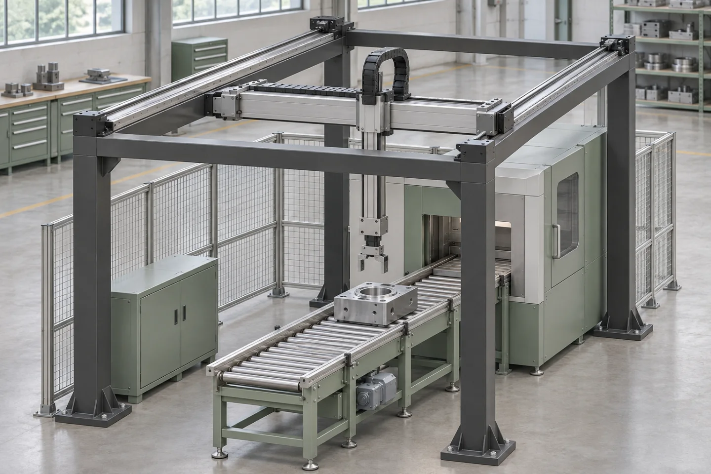
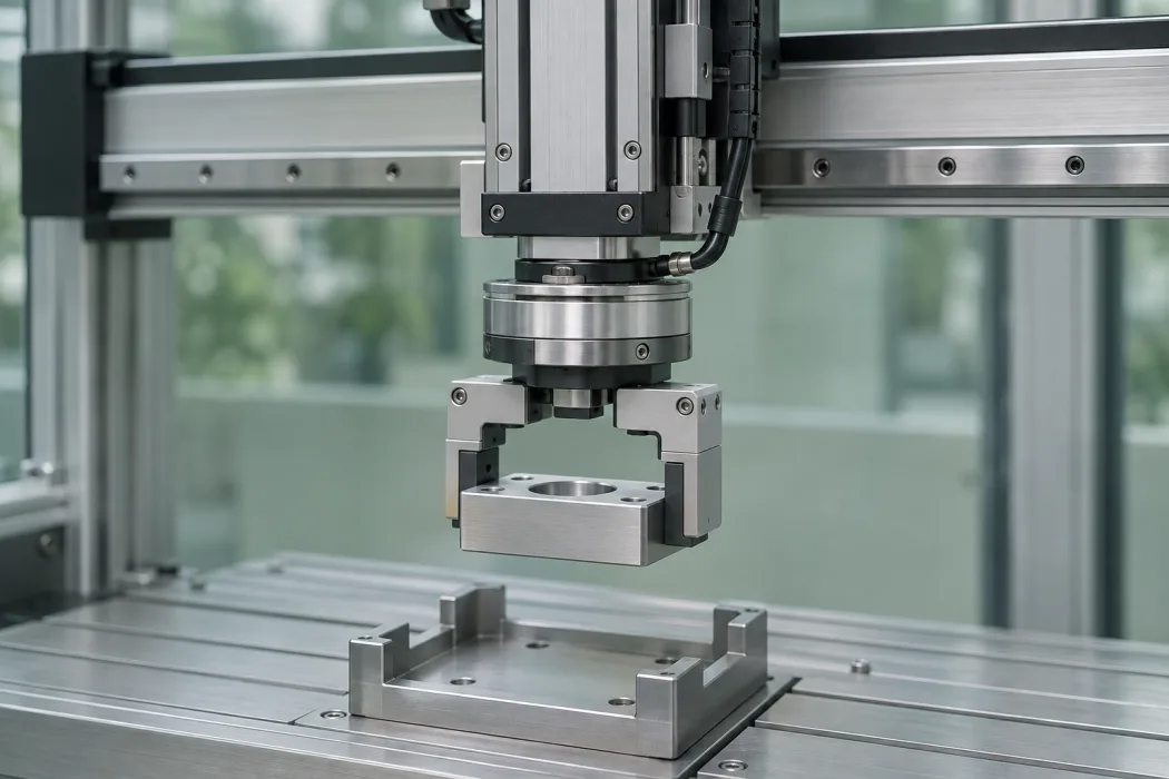
The bridge travels on two rails. A carriage moves across the bridge, and a vertical slide lowers the gripper to the part.
The bridge travels on the main rails between pickup and drop-off stations.
Pick parts from a tray or conveyor, place them in a fixture, then transfer them to the outfeed.
Move parts between consecutive operations such as assembly, inspection, or packaging.
Place finished parts on pallets, in bins, or on trays using the required pattern.
There are three basic motion layouts for this comparison: linear XZ, planar XY and three-dimensional XYZ. The other two examples show a cantilever structure and a rotary tooling option.
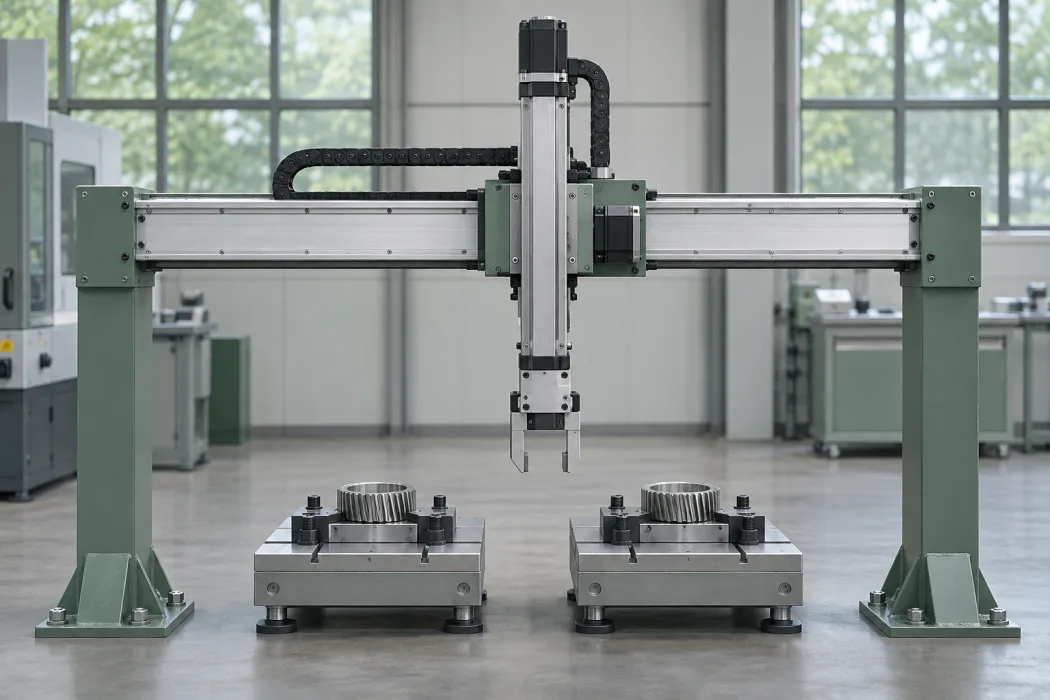
X + Z
A carriage travels on a fixed bridge supported at both ends. A vertical slide lowers the gripper to the pickup or drop-off height.
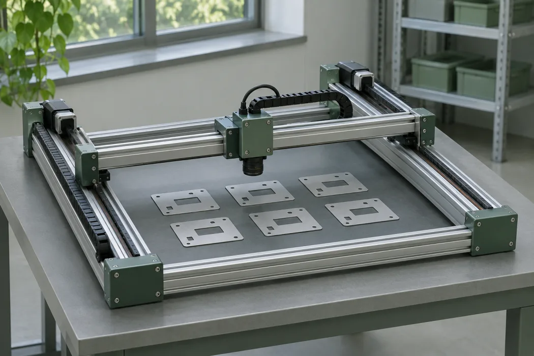
X + Y
A moving bridge travels along two parallel rails. A carriage moves across the bridge to cover a horizontal working area.
X + Y + Z
The bridge, transverse carriage and vertical slide provide three linear movements. The gripper can reach different stations within a rectangular working volume.
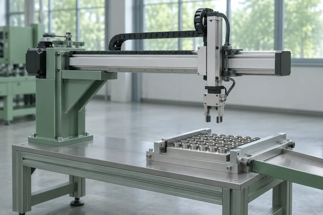
X + Z · open side
The arm is supported on one side. Its open end reaches stations that need front or side access. Cantilever refers to the mechanical layout and can be used with different axis counts.
XYZ + θ
A rotary axis at the gripper supplements the three linear movements, allowing the part to turn about the vertical axis as required.
A conveyor, tray, pallet or fixture presents the part at a pickup point. A sensor or machine signal can confirm arrival.
The gripper takes the part. The axes carry it through the available space between machines and stations.
The part is delivered to a fixture, outfeed or pallet. The cell returns to position for the next cycle.
Travel is the distance required on each axis. Cycle time includes movement, gripping, machine readiness and release, alongside axis speed.
The moving load includes the part, gripper and adapters. Mechanical jaws, vacuum or custom tooling may suit different parts. Reach and centre of gravity affect the choice of frame.
Pickup points, fixtures, part detection and machine ready/complete signals are considered together. Guarding, safety functions and maintenance access are part of the layout.
Attach your part drawing and line layout to the quote form if available. We use these details to assess axis travel, payload, and gripper selection.
Share your feeding projectYour questions, clear answers.
Yes. We assess work from a single component to larger manufacturing and machine projects. Production methods and scope depend on the part, material, quantity and requirements.
Both are possible. Machining, welding, assembly, blasting and painting can be planned separately or together. Automation, electrical, hydraulic and pneumatic services are scoped for each project.
OSEL Makine's machining facility is equipped with CNC vertical machining centers with a 3,500 × 1,500 mm table capacity and CNC turning lathes up to Ø900 mm diameter. Depending on geometry and material, high-precision machining is achieved within a total tolerance band down to 0.002 mm.
Share a drawing if available, material, quantity, critical dimensions and your required delivery date. A sample or photograph can support an initial review; technical information needed for production is then clarified.
Çevrimiçi